Cargo-Planner Docs
Container components
Use the Components tab in the container editor to model the geometry that lives inside a container: corner posts, structural frames, internal walls, mezzanine floors, and arbitrary blocks that occupy space or provide a loading surface. The load plan treats each component as a solid shape the solver must place cargo around.
Open a container from Equipment in the main navigation, then select Components. Editing library equipment requires the Equipment Editor permission.
Adding a component
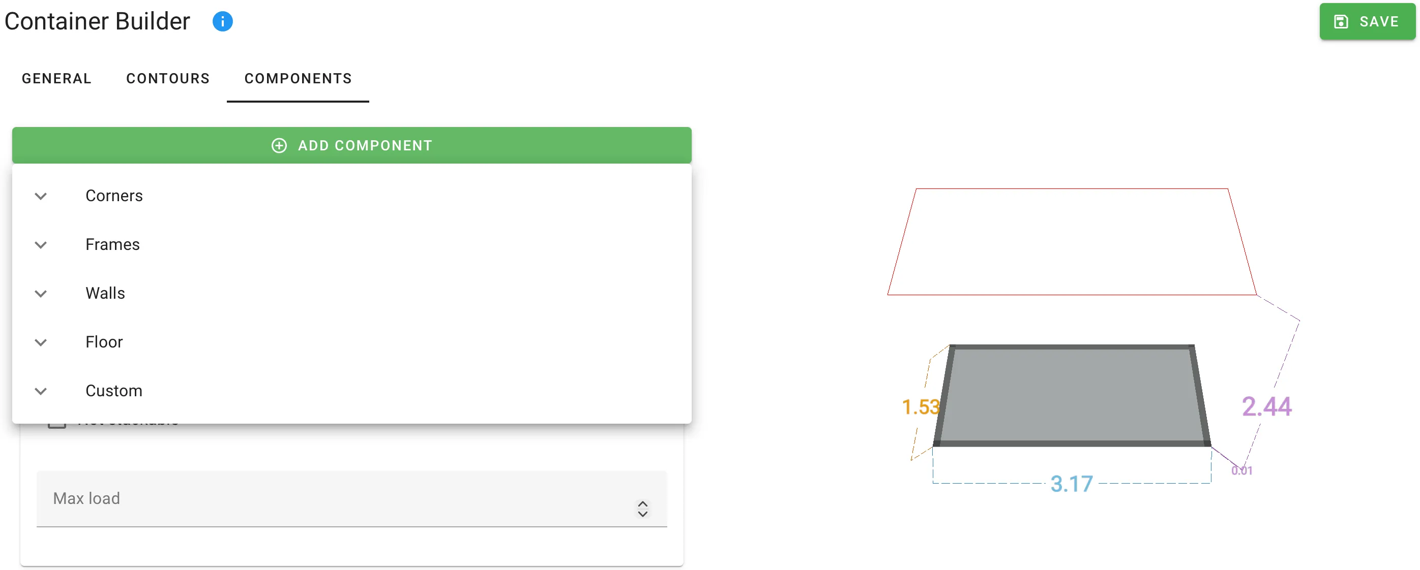
Click Add Component to open the picker. Presets are grouped by category:
| Category | Presets |
|---|---|
| Corners | Bottom rear corners · Bottom front corners · Top rear corners · Top front corners |
| Frames | Bottom end frames · Bottom side frames · Top end frames · Top side frames |
| Walls | Crosswise wall · Lengthwise wall |
| Floor | Floor |
| Custom | Custom part |
Each preset pre-fills sensible dimensions and anchor sides. Pick the closest preset, then edit its fields.
Component fields
Every component uses the same six-field layout. The title of each card shows the position number and the component’s raw type in upper case (1 - WALL, 2 - CORNER, 3 - FLOOR).
| Field | Meaning | Unit |
|---|---|---|
| L, W, H | Dimensions of the part along the length, width and height of the container. Individual dimensions are hidden when the Stick to selection makes them redundant — see below. | Length |
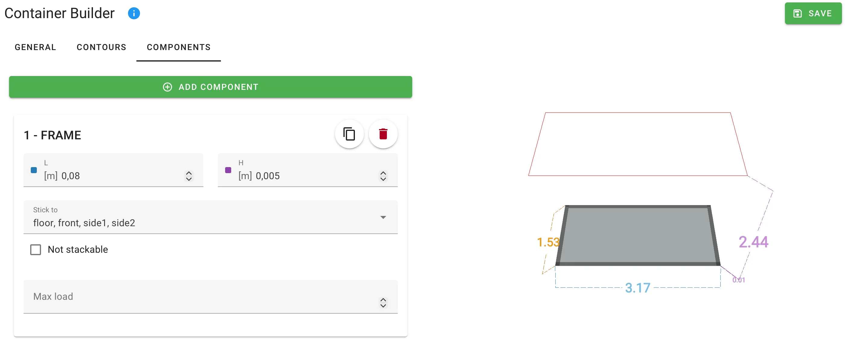
| Stick to | Which sides of the container the part is anchored to. Multi-select over Front, Rear, Side 1, Side 2, Floor, Roof. | — |
| X, Y, Z | Position of the part inside the container, measured from the front-left-floor corner. Individual axes are hidden when the corresponding Stick to sides are set. | Length |
| Not stackable | When on, cargo cannot be stacked on top of this part. Hidden entirely when the part is anchored to the Roof. | Boolean |
| Max load | Maximum weight the part can support on its top surface. Only shown when Not stackable is off. | Weight |
How Stick to works
Anchoring a part to opposite sides stretches it between them and hides the dimension that no longer applies:
- Stick to Front + Rear → the part spans the full container length; the L input disappears.
- Stick to Side 1 + Side 2 → the part spans the full width; the W input disappears.
- Stick to Floor + Roof → the part spans the full height; the H input disappears.
The same logic hides the corresponding X / Y / Z position input, because a spanning part has no free position on that axis.
Common shapes
Mezzanine floor
Add a Floor preset, set the Z position to the mezzanine height, and Stick to Side 1 + Side 2 so the floor spans the full width. Leave Not stackable off and set Max load to describe what the mezzanine can carry.
Weight limits by section
To give each section of a trailer its own weight limit - for example the front, middle and rear - add one Floor per section. Stick each to Floor + Side 1 + Side 2 so it lies on the container floor across the full width, give it a small H, and set X and L so the floors cover consecutive stretches of the length. Then set a different Max load on each. Max load caps the total weight of all cargo resting on that floor, and the planner never exceeds it, so each section is limited separately.
Corner posts
Use one of the Corners presets — they pre-select the correct Stick to combination (e.g. Bottom + Front + Side 1) and start with a small footprint. Adjust W, H and L to the actual post dimensions.
Internal partition wall
Add a Crosswise wall or Lengthwise wall preset. Set the X (or Y) position to the split point. Leave Not stackable on unless the wall is designed to hold cargo.
Related
- Front and rear decks — for raised platforms at the ends of the trailer only.
- Contours — for tapered corners of the container envelope.
- Custom containers — the end-to-end walkthrough for building a container from scratch.